

Industrial valves, glossary and definitions
In this basic-level document we aim to provide a first approach to the field of industrial valves. It is of didactic interest, from a training point of view, for staff recently joining valve distribution companies.
Manual Index
1. Introduction
Valves were already in use in Roman times and during the Islamic colonisation of Spain, as shown by the remains found of rudimentary stone objects that served to interrupt or divert the flow of water. However, the true appearance of valves in our world dates from the Industrial Revolution and the use of steam as a form of energy capable of keeping machines running. It is from the 20th century onwards when, as with the rest of engineering and industrial equipment, valves developed from their primitive designs to the sophisticated and specific ones of today.
In our industrial environment we could not conceive the non-existence of valves; in a hydraulic piping system there are three main elements: the pump, which produces the pressure needed to drive the fluids, the pipes that carry these fluids and, naturally, the valves, in charge of controlling the fluids. Without valves, fluids would travel through the pipes with no possibility of being used for their purpose.
How would we define valves?
Valves are mechanical devices whose function is to control fluids in a piping system. The European Committee for Standardization (CEN), in its standard EN-736-2, defines valves as that piping component which makes it possible to act on the fluid by opening, closing or partially obstructing the passage area, or by diverting or mixing it.
Some common parts of valves:
Valves, regardless of their type, have some common parts needed to carry out their function:
* Observe the main parts of a valve in the following typical valve (globe valve)
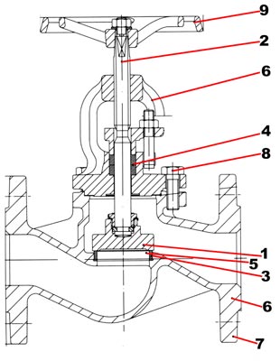
1-Closure member: also called a disc when it is a metal part, it is the piece that physically interrupts the fluid.
2-Stem: also called a spindle, it is the part that guides and holds the closure member.
3-Seat: part of the valve where closure takes place, through contact with the closure member.
4-Stem packing: the part fitted around the metal stem that ensures tightness of the fluid to the atmosphere.
5-Closure seals: the part fitted around the closure member (in some cases) that ensures a more perfect tightness of the closure member.
6-Body and bonnet: pressure-retaining parts, they are the enclosure of the internal parts of the valves.
7-Ends: part of the valve that allows connection to the pipe. They may be flanged, welded, threaded, grooved or not exist at all, that is, allowing the valve to be fitted to the pipe only by the external joints (wafer).
8-Bolting: the elements that join the body and bonnet of the valve to each other. To ensure atmospheric tightness, gaskets must be placed between these two metal surfaces,
9-Operation: the mechanism that operates the valve.
2. Types of industrial valves
According to their purpose of application we can find a first classification as follows:
- Isolation: its mission is to interrupt the flow of the line completely and whenever required.
- Check: its mission is to prevent the flow from returning towards the pressurised area when it decreases or disappears.
- Control: its mission is to modify the flow in terms of quantity, divert it, mix it or operate it automatically.
- Safety: used to protect equipment and personnel against overpressure.
Now, within each type of valve by its function we will find other classifications that will define different types of industrial valves in a more exhaustive way.
3. Isolation valves
Also called shut-off, stop, block or cut-off valves by virtue of their purpose within the fluid system. Isolation valves can be classified into two large groups according to the movement they make to obstruct the fluid:
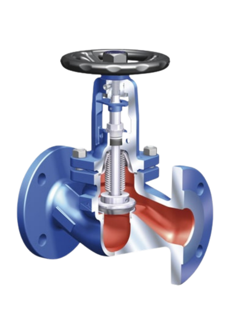
Linear isolation valves are those whose stem movement is made vertically from top to bottom for the closing action and from bottom to top for the opening action. They are characterised by slow closing and opening movements, operated by a multi-turn handwheel. They are essential when handling compressible fluids such as steam, so that slow closing does not cause hydraulic phenomena that could damage the valve and the general system.
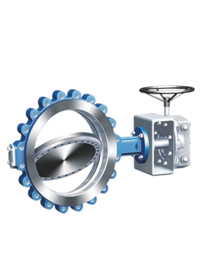
Rotary isolation valves are those whose stem movement is made in a rotary way through 90º as the full travel. They are characterised by fast closing and opening movements. They are normally used to transfer non-compressible fluids in liquid state and at low working pressures. The operating control is usually a hand lever.
3.1 Types of linear isolation valves
Within linear isolation valves we can detail the following types of valve as the most common.
- Globe valves
- Gate valves
- Diaphragm valves
3.2 Types of rotary isolation valves
Within rotary isolation valves we can detail the following types of valve as the most common.
- Ball valves
- Butterfly valves
3.3 Types of isolation valve according to their operation
Manually operated valves are the simplest; they must be handled by the plant operator by hand and, for this very reason, they must be accessible and, normally, the action is not carried out very often since the process does not require it.
Self-operated valves are those in which the fluid of the line itself, or contained within the valve, causes the movement of the stem or closure member. They are normally used in less accessible places and where the repetition of cycles is higher and dependent on some process parameter (control of temperature, pressure, level, flow…).
Valves operated by auxiliary power are those in which the action of an external power source causes the movement of the stem. This may be electric, pneumatic, hydraulic or hydropneumatic, as the most common. They are used for the automation of industrial processes with high repetition and accuracy in control.
4. Check valves
Check valves are those which, operated by the pressure of the fluid itself, allow it to pass and prevent it from returning towards the pressurised part when the system pressure ceases. They are unidirectional valves that open in one direction of flow and are closed in the opposite direction of flow (observe the installation instructions in our manuals). There are various types of check valve according to their design:
- Swing check valves
- Tilting disc check valves (“Tilt Check”)
- Split disc or dual plate check valves
- Spring-loaded disc check valves
- Ball check valves
- Lipped check valves
- Piston type check valves
Basically, the use of one design or another, given that they all perform the same function, is based on the user’s selection criteria: pipe connections, construction materials, lower pressure losses, nature of the fluid (for example loaded, viscous or dirty fluids… etc.), maintenance, temperatures and pressures.
5. Control valves
Control valves, also called regulating valves, are those that modify the amount of fluid in a system. The most common control valves are those operated by an external power source (electric or pneumatic, for example). These valves are considered the final element of the control system through which the fluid circulates and are normally used in processes where continuous movements and precise control are required. Of course, not all control valves are operated by external power sources; manually operated valves with a characterised, conical or parabolic closure member would also be considered as control valves. On the other hand, self-operated valves are considered open/close valves (On/Off) since they do not allow partial modifications of the fluid, even though the function they perform within the system is to “control” a process.
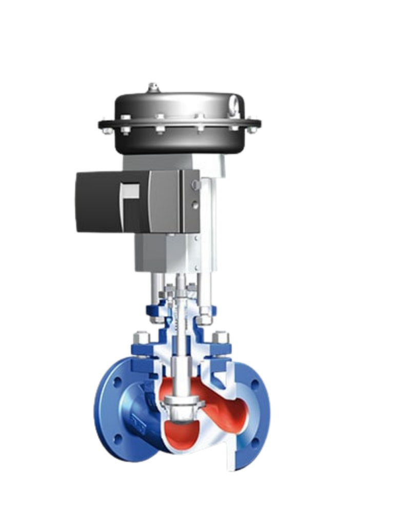
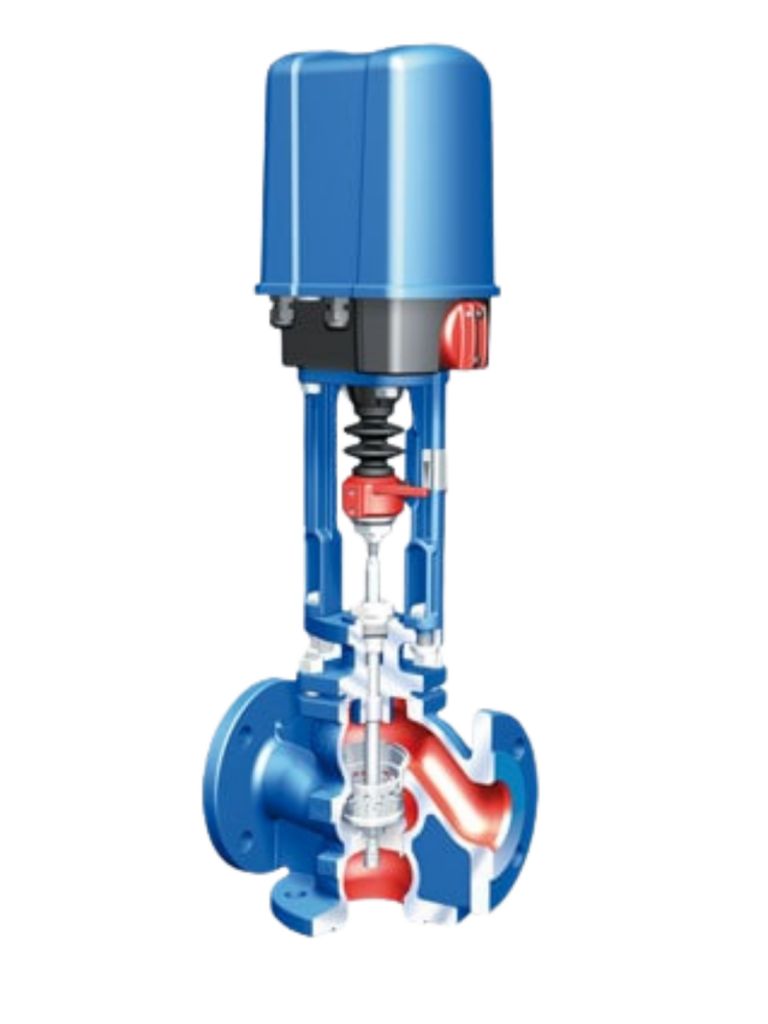
Control valves cannot be understood without observing the so-called “control loop” that makes up the system. This loop is made up of an electronic controller that collects the input signal (desired control parameters); the valve actuator, the valve itself and the sensing element of the system.
The desired parameter to be controlled is entered into the controller (1); the actual parameter measured in the system is fed to the controller and, if these parameters do not match, it generates an error signal that transfers the action to the actuator (2) of the valve (3), carrying out the closing (reduction of flow) or opening (increase of flow). The sensing element (4) installed downstream of the valve measures the flow and sends the signal to the controller, completing the closed loop.
Control valves can be designed with a straight-through passage but also with three-way passages to perform mixing or diverting functions:
Mixing valves are those designed to act on the proportion of two or more inlet fluids to produce a common outlet fluid by changing the position of the closure member.
Diverting valves are those designed to act on two or more outlet fluids from a common inlet fluid by changing the position of the closure member.
6. Safety and pressure relief valves
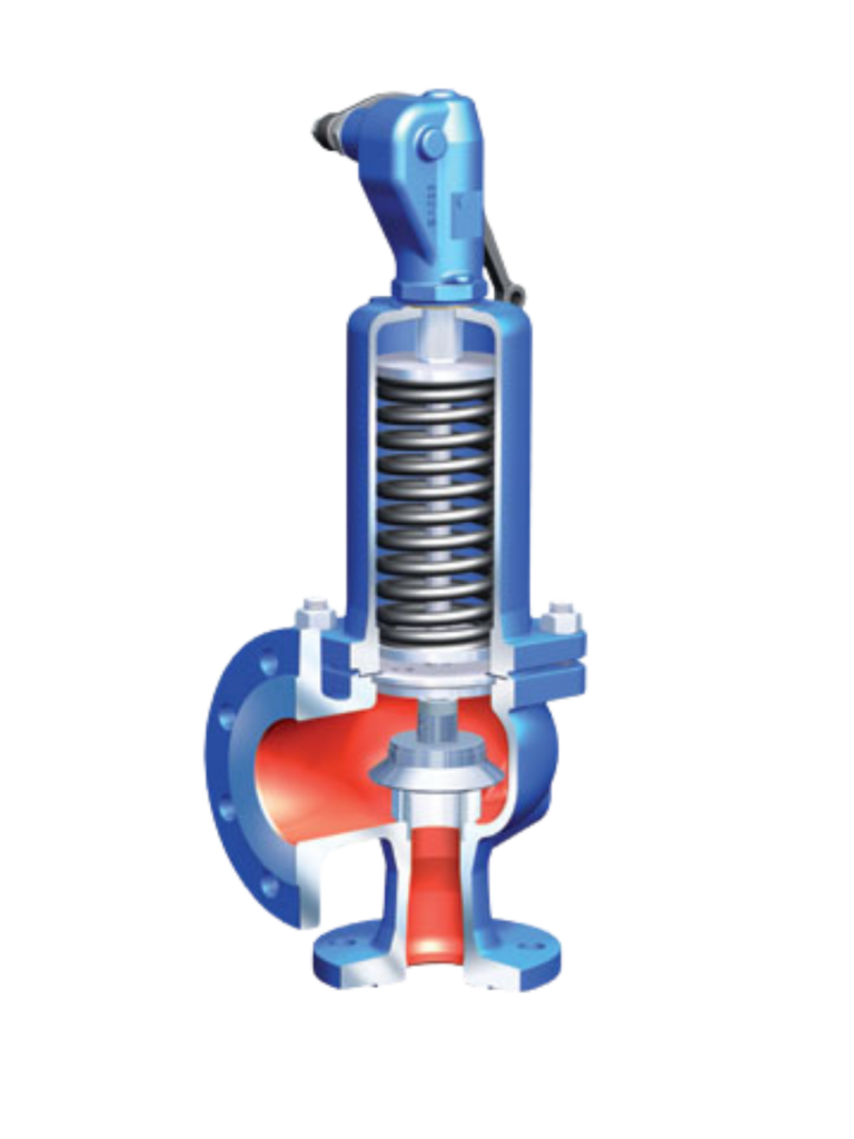
Safety and relief valves are devices self-operated by the fluid that prevent overpressure in pressurised vessels, lines and other general equipment. The valves are usually designed at a 90º angle to make it easier to discharge the fluid from the system. The valves consist of a spring preset to a given set pressure, above which it will act by releasing the fluid from the system; once the fluid has been discharged and the working pressure restored in the system, they return to their initial closed position. The use of safety valves is essential in pressurised vessels, since compressible fluids would cause, in the event of a pressure increase above that conceived in the design, their deformation or rupture, with the danger to people and property that this entails.
There are various types of safety valve designed under various codes to meet the needs of today’s industry.
7. Glossary of terms and definitions
Main types of linear isolation valves
Globe valves:
They are valves with a curved body design to favour the circulation of the fluid and whose closure member is a disc that closes against a finely machined seat to achieve tightness. The fluid enters the valve below the disc, being unidirectional. Atmospheric tightness is achieved with packing rings placed around the stem.
Bellows sealed valves:
Basically they are valves of the same design as conventional globe valves, but characterised by having a metal bellows that performs the function of atmospheric tightness, thus requiring no maintenance in the plant.
Flow balancing valves:
They are seat valves with a control characteristic, fitted with a flow meter and upstream and downstream tappings on the valve to facilitate the balancing of the flows circulating through the valve.
Gate valves:
They are isolation valves characterised by closing by means of a flat-faced disc (wedge) that slides vertically over the fixed seats of the valve placed in parallel. They are bidirectional valves, of great capacity and not suitable for control duties.
Knife gate valves:
They are a derivation of gate valves but with a closure member consisting of a flat plate with a knife edge to cut viscous fluid. Unlike the former, these are unidirectional and are usually designed as WAFER or LUG type for mounting between flanges.
Diaphragm valves:
They are shut-off valves characterised by closing by means of a flexible and deformable element (diaphragm), which is operated by a compressor attached to the stem. In the concave position the diaphragm allows the fluid to pass, with the valve open, while in the convex position it prevents the passage of the fluid, with the valve closed.
8. Main types of rotary isolation valves:
Butterfly valves:
Butterfly valves are valves that have a circular disc which is turned on a stem, obstructing the passage section of the duct when it is perpendicular to its axis and leaving the passage free when it is parallel. The disc achieves partial or total opening angles of up to 90º that allow the fluid to pass.
The common name “butterfly” is attributed to the shape of the disc, consisting of a central rib through which the stem passes, with flat outer faces resembling the body of the insect with its wings.
There are various types of butterfly valve according to the position of the stem in its rotation operated by the manual control: concentric valves, double eccentric valves and triple eccentric geometry valves. More detailed information on each of these types of butterfly valve can be obtained in our manuals and data sheets, available for download on our website www.comeval.es
Ball valves:
Also known as “ball” valves, it is a mechanism used to regulate the flow of a channelled fluid and is characterised by having the shape of a drilled ball. The regulating mechanism located inside is opened by turning the stem attached to the drilled ball, in such a way that it allows the fluid to pass when the drilling is aligned with the inlet and the outlet of the valve. When the valve is closed, the hole will be perpendicular to the inlet and the outlet. The position of the operating lever indicates the state of the valve (open or closed).
There are various constructive types of ball valve according to their construction; nevertheless, the two commonly defined categories are based on the combined movement of the ball with the stem, these being floating ball valves and trunnion-mounted ball valves. Floating ball valves are the most conventional, and in them the stem operates the ball from the upper part only. Valves with a TRUNNION design are characterised by upper and lower guiding of the ball. It is usually the design used in the largest sizes.
Plug valves:
Plug valves are a variant of ball valves with a similar operating principle, but with a tapered plug which allows the fluid to pass when it is aligned with the axis of the pipe. The plugs may be sleeved or lubricated.
Our M-3 Module analyses Safety and Relief Valves in greater depth; for more details about it you can tell us you are interested or send us your enquiries to our training mailbox.
Our technical specialists are available for any general or particular request about this chapter. Contact us through the enquiries mailbox formacion@comeval.es
9. Basic criteria for selecting valves
9.1 Choosing the type of valve according to its function
Our first basis for choosing will be based on the function that the valve or equipment must perform in the plant; for this we will distinguish the following functions:
- Isolation: we want to interrupt the flow of the line completely and whenever required.
- Check: we need to prevent the flow from returning towards the pressurised area when it decreases or disappears.
- Control: we want to modify the flow in terms of quantity, divert it, mix it or operate it automatically.
- Safety: we need to protect equipment and personnel against overpressure.
Now, within each type of valve there are very different designs that respond to the demands of the plant, the installation, the types of materials and availability.
9.2 Determining the nominal pressure
The next factor is to determine the rating or nominal design pressure of the valve. This factor is determined by the process data in the plant, mainly by the intersection between the effective working pressure and the effective working temperature. There are standard design pressures or manufacturing ratings to specify against; these differ between the DIN and ANSI standards, and the most common are shown in the following table with their closest equivalence:
| DIN | ANSI |
|---|---|
| PN 10 | Class 125 |
| PN 16 | Class 150 |
| PN 25 | Class 300 |
| PN 40 | Class 600 |
| PN 64 | Class 900 |
| PN 100 | Class 1500 |
| PN 250 | Class 2500 |
These nominal pressure classes should only be taken as a selection of the valve according to the intersection curve between the pressure and the maximum temperature of the process. We must always consider that the maximum pressure decreases as the temperature increases, and vice versa.
9.3 Determining the construction materials
According to the previous factor (pressure x temperature), as well as the chemical compatibility and the resistance to corrosion and erosion of the fluids, we must choose the construction materials of the various parts of the valve.
From the point of view of selecting the materials of a valve we must always consider the following:
- Pressure-retaining body, wetted part in contact with the fluid.
- Soft parts and packing
- Bolting and external coatings.
For the body we will check that the available material is compatible with the fluid in terms of chemical compatibility (see the Material Compatibility Finder located in our Utilities section on the entry portal of our website). We will observe not only this compatibility but also other factors related to abrasion (line speed or nature of the fluid); in these cases we can select an internal lining that, keeping the base metal material, prevents contact between the flow and it (for example: soft natural rubber lining in the case of “slurry” fluids in mining).
To determine the material of the packing or internal and external sealing, the temperature and the compatibility of the sealing material with the fluid will be decisive. In this case the temperature limits recommended by the manufacturers of the gaskets and packing must be observed (for example: do not exceed 90ºC in the case of NBR). The sealing of the valve is essential; we distinguish two types of seal: sealing to the closure member (internal) and atmospheric sealing (external).
Finally, although of lesser importance, we will observe the material joining the parts, understood as the bolting and the external paint coatings. This factor is important solely for the purposes of environmental corrosion in the plant (for example: saline or corrosive atmosphere… etc.).
9.4 Choosing the operation
Valves can be operated in various ways:
- Manually
- Self-operated by the fluid itself
- Operated by external actuators
The selection of the type of operation is conditioned by the needs in the plant; for example accessibility to the valve, frequency of operation, availability of auxiliary power, economy, degree of accuracy required in the operation…, these factors fall within the particular circumstances of each project.
9.5 Choosing the valve size (DN)
Valves are standardised to a nominal size or diameter according to international standards. The sizing of the valve is carried out according to the flow circulating in the line and other process factors. When selecting the valve we have to consider aspects such as cavitation and differential pressure, among others.