

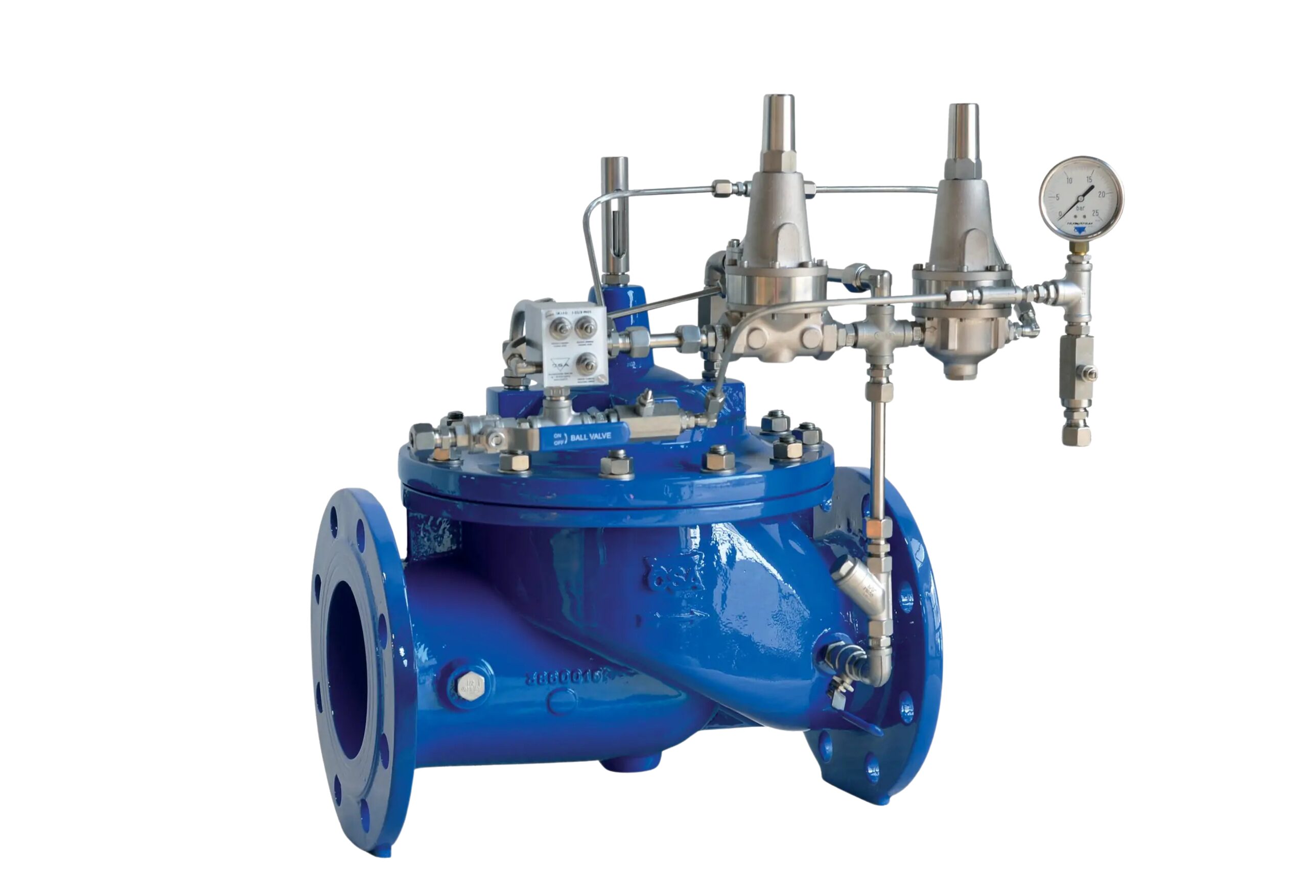
Technical description
The control valve is installed as a branch off the main pumping line. It acts as an upstream pressure relief valve. By means of a low pressure pilot, in the event of pump failure the pressure drop is detected and the pilot opens, connecting the control chamber to atmosphere and thus opening the valve before the positive pressure wave arrives.
Features
• GJS 450-10 ductile iron body and cover.
• GJS 450-10 ductile iron and stainless steel internal components.
• Stainless steel position indicator.
• Stainless steel pilot circuit.
• Stainless steel adjusting device, needle valves and flow stabilisers.
• Stainless steel seat.
• RAL 5005 blue epoxy coating applied by fluidised bed technology.
Applications
• Pressure relief and protection during pump start-up.
• Water hammer protection in the event of a sudden pump stop caused by power failure, thanks to the anticipating effect of the low pressure pilot, and overpressure protection by the high pressure pilot.
Reference standards and flanges
• Designed and tested to EN 1074.
• Flanges from DN 50 to DN 400 mm, larger sizes on request.
• Flanges to EN 1092/2, others on request.
Working conditions
• Pressures: 10-16-25 bar.
• Minimum pilot pressure: 1.5 bar.
• Clean water up to 70ºC, version for higher temperatures on request.
Technical identification
Markets
Applications
Resource Library
Control valves
PDF comeval-diptico-CSA-ESP.pdfCSA catalogue
PDF DS_SP_1610_CSA_COMPLETE.pdfAutomatic control valves - PN16-25
PDF CSA-Valvulas-de-regulacion-automaticas-8.2017.pdfAutomatic control valves - PN40
PDF CSA-valvulas-XLC-500-600-.pdfNo documents of this type available.
No documents of this type available.